Power rails, boot current & oscilloscope diagnostics
When a multi-rail board — an ESP32 dev board, a compute carrier, or a laptop mainboard — refuses to boot, checking single resistors is not enough. You need to follow the power tree: how an input supply steps down through standby rails, enable signals, switching converters, and power-good chains.
1. Reading boot current like a log #
Before probing a complex board blindly, power it from a bench supply and watch the milliamps. Boot current tells you which stage of the power sequence stalled:
$ power on --supply 30V --rail 30V_GATE
G3H   standby .....................  0.0 mA
seq   S5 → S4 → S3 → S0 ...........  0.0 mA
S0    +5V +3V3 +1V2 up ............ 10.3 mA
S0    loads settle ................ 16.2 mA
ok    board alive
(Laptop schematics often label rails by ACPI power states: G3H always-present standby, S5 soft-off, S4/S3 suspend/memory, and S0 running. Boards whose rail names carry no power states — like many open-hardware boards — enable their converters directly once input voltage and enable pins are valid.)
| Bench supply reading | What it usually means | Where to measure next |
|---|---|---|
0.0 mA completely flat |
Power isn't entering the board, or primary input (G3H / VIN) is open. |
Fuse, input connector, reverse-polarity diode, primary VIN trace. |
| Stuck at low standby (few mA) | Standby rail is up, but a downstream EN (enable) or PGOOD never arrived. |
Regulator VIN, EN pin, PGOOD, or under-voltage lockout (UVLO). |
| Rhythmic pulsing / looping current | Boot loop: a converter tries to start, hits overcurrent or input brownout, resets, and retries. | Oscilloscope in Roll mode on the sagging rail and switch node. |
| High constant draw / hits CC limit | Hard short or heavy leak on VIN or an always-on rail. |
Power off → Ω to GND across inductors/rails, then injection + thermal / rosin / IPA. |
2. Linear regulators, buck converters & chargers #
Most modern boards combine three kinds of power stages:
Linear regulators (LDOs) #
An LDO (such as an AMS1117-3.3 or AP2112) drops Vin − Vout as heat:
P_ldo = (Vin − Vout) × Iload
- Check
VIN,EN, andVOUT: IfVINis5.0 V,ENis high, andVOUTis0 V, turn power off and measureVOUTtoGNDbefore blaming the LDO. A blazing-hot LDO is frequently healthy — it is just dumping current into a shorted decoupling capacitor downstream! - Check feedback resistors (
FB): Adjustable LDOs and converters setVout = Vref × (1 + R_top / R_bot). Wrong or drifted feedback resistors produce the wrong rail voltage (wrong 3.3 V), preventing downstream logic from starting or damaging it.
Buck switching converters #
Step-down switching converters chop VIN through a switch node (SW or LX) into an inductor and output capacitors:
VINpresent? No input voltage points to an upstream switch, fuse, or open trace.EN(Enable) high? Boards often chainPGOODfrom the5 Vrail intoENof the3.3 Vrail. If5 Vsags or drops out,3.3 Vshuts off too.SW/LXswitching? Probe the switch node (between the converter IC and its inductor) with an oscilloscope. Active rectangular switching pulses mean the converter is running; flat DC means it is disabled, missingVIN, or in protection.- Output shorted or high ESR? Check
ΩtoGNDon the output inductor with power off. On real hardware, degraded capacitors with high ESR cause severe switching ripple even when average DC voltage looks normal.
Li-ion battery chargers & USB power paths #
Boards with USB + Li-ion charging route VBUS through the USB connector, protection diodes, and a charger / power-path IC:
- If a board "only works on battery" and stays dead on USB, inspect the USB connector solder joints,
VBUStrace/diode, and the charger IC'sVIN/UVLOthreshold before suspecting the MCU. - Check the charger's
PROGcurrent-programming resistor (if open or wrong value, charging fails or misbehaves) andSTATstatus output.
3. Oscilloscope diagnostics (O) #
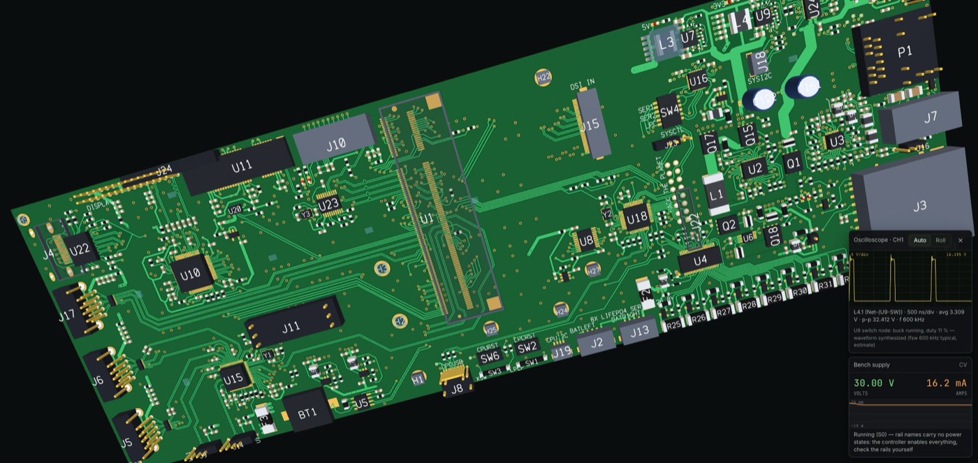
A multimeter averages slowly — it hides a rail that rises for 2 ms and collapses, and it cannot distinguish clean 3.3 V DC from a noisy sagging rail or an active switch node. Clip the oscilloscope (O in DEADBOARD) onto a net and match the mode to the question:
- Roll mode (slow timebase): Watch power-up ramps, rail sequencing (
5 Vrising before3.3 V), momentary dropouts, and boot loops where current and voltage pulse repeatedly. - Auto / Triggered mode (fast timebase):
- Switch node (
SW): Look for a clean switching square wave (duty cycle roughlyVout / Vinon a buck). - Output rail ripple: Use DC coupling to check absolute rail voltage (
3.30 V), and on a real bench scope switch to AC coupling (with a short ground spring, not a long alligator clip) to zoom in on millivolt ripple without picking up stray switching ringing. - Clocks & crystals: Verify whether an oscillator (
32.768 kHzRTC crystal,24 MHzMCU crystal) is oscillating once its driver chip has power, rather than sitting at flat DC.
- Switch node (
Honest note on DEADBOARD's scope: Roll mode plots real voltages recorded from successive circuit solves over time (real ramps, droop, and boot loops). Because the circuit engine solves averaged DC operating points rather than nanosecond switching cycles, Auto mode synthesizes representative switch-node square waves (
~600 kHztypical estimate), output ripple (~0.8%p-p estimate), and named clock nets (32K,24M, etc., active only when powered) from the solved state — and labels those synthesized traces clearly on screen.
4. Boardview, schematics & intermittent faults #
On boards with 50 to 500+ parts, tracing copper by eye alone breaks down:
- Boardview + Schematic together: Click any pad or component in DEADBOARD to highlight its net across Top, Bottom, and vias, then match the reference designator (
U3,R12,C44) and net name (+3V3,30V_GATE,VBUS) against the Schematic tab. - Thermal intermittents: Some cracked parts or weak silicon only open or leak once warm. If a board starts normally and fails seconds later, watch Thermal view or gently warm suspect areas with Hot air (
H) while watching the rail voltage, and test Freeze spray (9) to see if cooling restores operation. - Flex / cracked joints (
BPress / flex): Cracked solder joints under connectors (like a yanked USB port) or BGA/QFN packages can pass continuity at rest and fail when flexed. Use Press / flex (B) while monitoring rail voltage or LEDs to expose mechanical intermittent faults.
Practice power-rail diagnostics on the bench #
- Olimex ESP32-DevKit-LiPo — Dead on USB and won’t charge (50 parts)
- Rana Tadpole V1 — Dead on USB across a flat-cable breakout (56 parts)
- ESP32-C3 Rust board — Rails look fine, chip stays asleep after a spill (55 parts)
- Antmicro Jetson baseboard — Missing 3.3 V and flaky 5 V rail (369 parts)
- MNT Reform 2 mainboard — Dead 3.3 V rail on a 522-part laptop mainboard